Chemical and physical origins of friction on surfaces with atomic steps
Abstract
CODIRECT, financed by VINNOVA and the Swedish Foundation for Strategic Research (SSF) at the Institute for Surface Chemistry
Friction occurs through a complex set of processes that act together to resist relative motion. However, despite this complexity, friction is typically described using a simple phenomenological expression that relates normal and lateral forces via a coefficient, the friction coefficient. This one parameter encompasses multiple, sometimes competing, effects. To better understand the origins of friction, here, we study a chemically and topographically well-defined interface between silica and graphite with a single-layer graphene step edge. We identify the separate contributions of physical and chemical processes to friction and show that a single friction coefficient can be separated into two terms corresponding to these effects. The findings provide insight into the chemical and topographic origins of friction and suggest means of tuning surfaces by leveraging competing frictional processes.
INTRODUCTION
Friction occurs at the interface between any two solid surfaces that are in contact and moving at different speeds or directions. Friction corresponds to wasted energy and therefore determines the efficiency and useful lifetime of all moving systems, from biological to aeronautical. At the macroscale, friction force (Ff) is often linearly proportional to the applied load (L). The proportionality constant of this relationship is called a friction coefficient [or coefficient of friction (COF), typically given the symbol μ]; thus, it can be expressed as Ff = μ × L, which is the well-known Amonton’s law (1). At the nanoscale, adhesive forces (Fa) become significant and an additional term is introduced, Ff = μ × (L + Fa) (2). Although this expression is phenomenologically simple and has been found to hold valid in experiments for decades, the actual mechanisms determining the magnitude of the COF are very complicated. Friction has been proposed to have purely physical origins (3, 4) and to be related to chemical processes in sliding interfaces (5, 6). However, the interplay of these two effects that ultimately results in observed friction is still poorly understood because often friction is associated with surface wear. In this study, we used a chemically and topographically well-defined interface to identify the contributions of physical and chemical processes to friction without wear and thereby obtain fundamental insights into the origin of the frequently reported but poorly understood COF.
RESULTS
Figure 1 schematically depicts the model system used in this study, which consists of an atomic force microscopy (AFM) probe and a graphite surface with a single-layer graphene step edge. The basal plane of graphite provides a chemically inert and defect-free flat surface. Because the graphene sheet exposed at the top surface is commensurate with the underlying layer (i.e., all topmost atoms are in registry with the underlying atoms), it provides the topographically least corrugated surface for friction tests (7). The single-layer graphene step edge that can be found on the graphite surface provides a well-defined topographic corrugation with a height change of precisely 0.34 nm over a distance corresponding to one chemical bond length (8). The carbon atoms at the graphene step edge are terminated with hydroxyl (C─OH) and alkyl (C─H) groups (fig. S1). The AFM probe made of silicon is covered with a native oxide; thus, it is hereafter referred to as a silica tip. This same system is modeled using reactive molecular dynamics (MD) simulation of the apex of the silica tip and the topmost three layers of graphene in the graphite near the step edge (fig. S2). Thus, it allows both experimental and computational studies of the interfacial shear of a silica surface on both an atomically flat surface and a chemically and topographically well-defined feature at the step. Upon confirmation of agreement between the experimental and computational friction responses, the simulations provide insight into the atomic-level origins of the friction.

The silica tip model represents the native oxide at the apex of the Si AFM tip used in the experimental study. This model system enables both experimental and computational studies that isolate the chemical and physical origins of friction.
Figure 2 shows the lateral force and height profiles measured from the AFM tip sliding over the graphite basal plane and moving up and down the graphene step edge at an applied load of 36.7 nN in dry nitrogen. Both sides of the graphene step edges are the basal plane of the graphite crystal, where the friction force (half the difference between the trace and retrace lateral forces) is only 0.15 ± 0.03 nN on both the upper and lower terraces. If this friction force is divided by the sum of the adhesion force (9.4 ± 0.8 nN) and the applied load (36.7 nN), it corresponds to a COF of 0.003. This value is consistent with the superlubricity reported for other types of carbon surfaces (9–12). However, when the AFM tip climbs up the step from the lower terrace to the upper terrace, friction increases by 30 to 40 times (positive lateral force in the step-up direction), giving a COF of about 0.1. This value is close to COFs observed for boundary lubrications by organic molecules on various surfaces under elastic deformation regimes (13). In contrast, more complicated friction responses are observed when the AFM tip slides down from the upper terrace to the lower terrace. Note that when the sliding direction is reversed, friction corresponds to a negative lateral force. During the step-down, friction first increases (negative lateral force), then decreases (change to positive lateral force) during the topographic height change, then increases again, and finally reaches the basal plane value as the tip moves away from the step edge.

The normal force applied to the tip was 36.7 nN, and the sliding speed was 500 nm/s. In the step-up direction, the positive lateral force means that the graphene step edge is resisting tip sliding. In the step-down direction, the negative lateral force is resistive to the tip sliding and the positive (or upward deviation from the negative trend) force is assistive to the tip sliding. The inset is the AFM topographic image of the graphene step edge obtained after repeated friction measurements at applied normal forces varying from 7.3 to 36.7 nN (fig. S3A); the postscan image shows no damage of the friction-tested region (white line). The height of the step edge is 0.34 nm, corresponding to the sum of the thickness of one graphene layer and the interlayer spacing between adjacent graphene layers.
The changes in friction observed at the step edge (Fig. 2) cannot be explained by topography alone. If the topographic effect was dominant, then the trace and retrace hysteresis at the step edge should be the same as that on the basal plane and its center is shifted from the zero line (14). In the literature, the large friction (resistive force) during the step-down motion over various atomic steps has been explained in the context of a simple Prandtl-Tomlinson model with an additional potential barrier at the step edge called an Ehrlich-Schwoebel barrier (15, 16). The concept of the Ehrlich-Schwoebel barrier was adapted from the diffusion barrier for atomic movements at a surface encountered in film growth studies (17). Although this phenomenological model can reproduce experimentally observed friction behavior, it does not provide molecular or atomistic insights into the origin of the Ehrlich-Schwoebel barrier. Previous modeling studies reproduced this barrier and demonstrated its ability to describe step edge friction, but the models did not explicitly include chemical reactions (15, 16), so chemical and physical effects could not be differentiated. Here, to explore these origins, friction trends at the key points along the friction trace were analyzed as a function of load.
The trends shown in Fig. 2 were observed in AFM experiments performed at a range of loads (7.3 to 36.7 nN; fig. S3A) and sliding speeds (0.25 to 2 μm/s; fig. S3B), as well as reactive MD simulations performed at comparable pressures (fig. S4A). The experimentally observed trend is not a strong function of sliding speed (fig. S3C), and MD simulations performed at two sliding speeds exhibited the same trends (fig. S4B). The load dependence of friction on the graphite terrace and at the graphene step edge, from both experiment and simulation, is shown in Fig. 3. The qualitative trends from experiment and computation agree, despite differing size and time scale. This confirms that the simulations can provide atomistic insights into the interfacial processes responsible for complex friction behaviors at the single-layer graphene step edge as well as the superlubricity on the graphite basal plane.

(A) Friction force measured with the silica AFM tip under various applied normal loads. The step-up resistive, step-down resistive, and step-down assistive forces are determined as marked in Fig. 2. The mean and SD were calculated from values of multiple measurements, where each measurement involved averaging over 128 scans. The SDs of the experimental values are similar to or smaller than the size of symbols. (B) Friction force calculated from reactive MD simulations. Note that, for the step-down case, a positive assistive lateral force corresponds to a negative friction force. (C) COF calculated from the load dependence of friction force, which is the slope of the least squares fitting lines in (A) and (B). The error bar in (C) indicates the uncertainty in the calculated slope. Because friction force for the cases of step-down resistive and step-down assistive decreases as the applied load increases, negative COF is obtained.
The rate of change of friction with load at different positions along the friction trace is used to quantify COFs (Fig. 3), with the goal of isolating the chemical and physical contributions. The COF on the basal plane is in the superlubricity regime (18, 19). However, during step-up, the COF increases by orders of magnitude. The step-down behavior is more complicated, as it consists of both assistive and resistive forces. The resistive force (positive friction) decreases slightly with load, corresponding to a small negative COF (20). Lastly, the assistive force (negative friction) during step-down becomes larger in magnitude with increasing load, corresponding to a moderate negative COF. All of these measurements of friction are for the same materials sliding under the same operating conditions. The fact that there are drastic differences in the COF, including a change in sign, depending on the relative position of the tip with respect to the step, demonstrates that these results could be used to identify different factors that contribute to friction. The atomic-scale information in the simulations is used to explore this.
Figure 4 shows the lateral force calculated from MD simulations at a load of 10 nN, along with the topographic height change (Fig. 4, A and B). The shear strain of the silica tip is used to quantify physical contributions to friction (Fig. 4, C and D), and chemical contributions are quantified by the number of hydrogen bonds formed between silica and graphite surface (Fig. 4, E and F). Gradual changes in the out-of-plane fluctuation amplitude of the carbon atoms on the upper and lower terraces (fig. S5) suggest that the tip sliding over the graphene step edge is a smooth process. When the silica tip is on the basal plane of graphite, there is no change in strain and no hydrogen bonding interaction across the interface. This is consistent with the expectation that the interlocking between atoms across the interface is negligible because the amorphous silica structure and the two-dimensional hexagonal array structure of graphite are incommensurate (21), there is no buckling of the surface because the topmost graphene layer is in registry with the underlayer (22), and the basal plane of graphite is chemically inert (23, 24). There are no significant physical or chemical interactions causing friction, which explains the superlubricity (COF of ~0.003) observed for the silica tip sliding on the graphite basal plane.

(A and B) Lateral force, (C and D) shear strain of atoms in the silica where the sign indicates direction relative to sliding, and (E and F) number of hydrogen bonds formed between the graphene step edge and the silica, calculated from simulations as a function of center-of-mass position of the tip with respect to the graphene step edge for (A, C, and E) step-up and (B, D, and F) step-down. The normal load applied to the silica tip is 10 nN, and the sliding speed is 10 m/s. The topographic height change measured with the center of mass of the counter surface is shown with dashed lines in (A) and (B) on the secondary y axis. The white and gray background areas are the lower and upper terraces, respectively. The snapshots of the shear strain of atoms in the silica and the hydrogen bonds bridging two surfaces at three locations for both step-up and step-down are also shown.
As the silica tip steps up over the graphene edge, the shear strain of the atoms in the tip increases in the direction opposite of the sliding motion (Fig. 4C). The degree of shear strain is the largest just before the center of mass of the tip moves to the upper terrace. In addition, the hydrogen bonding interactions between the silica tip and the C─OH groups at the graphene edge increase during the step-up (Fig. 4E), accompanied by the out-of-plane deformation of C─OH groups terminating the step edge (fig. S6). So, at step-up, the physical (strain) and chemical (hydrogen bonding) mechanisms synergistically enhance resistance to sliding, leading to a COF more than 100 times larger than that on the basal plane of graphite.
Featured product
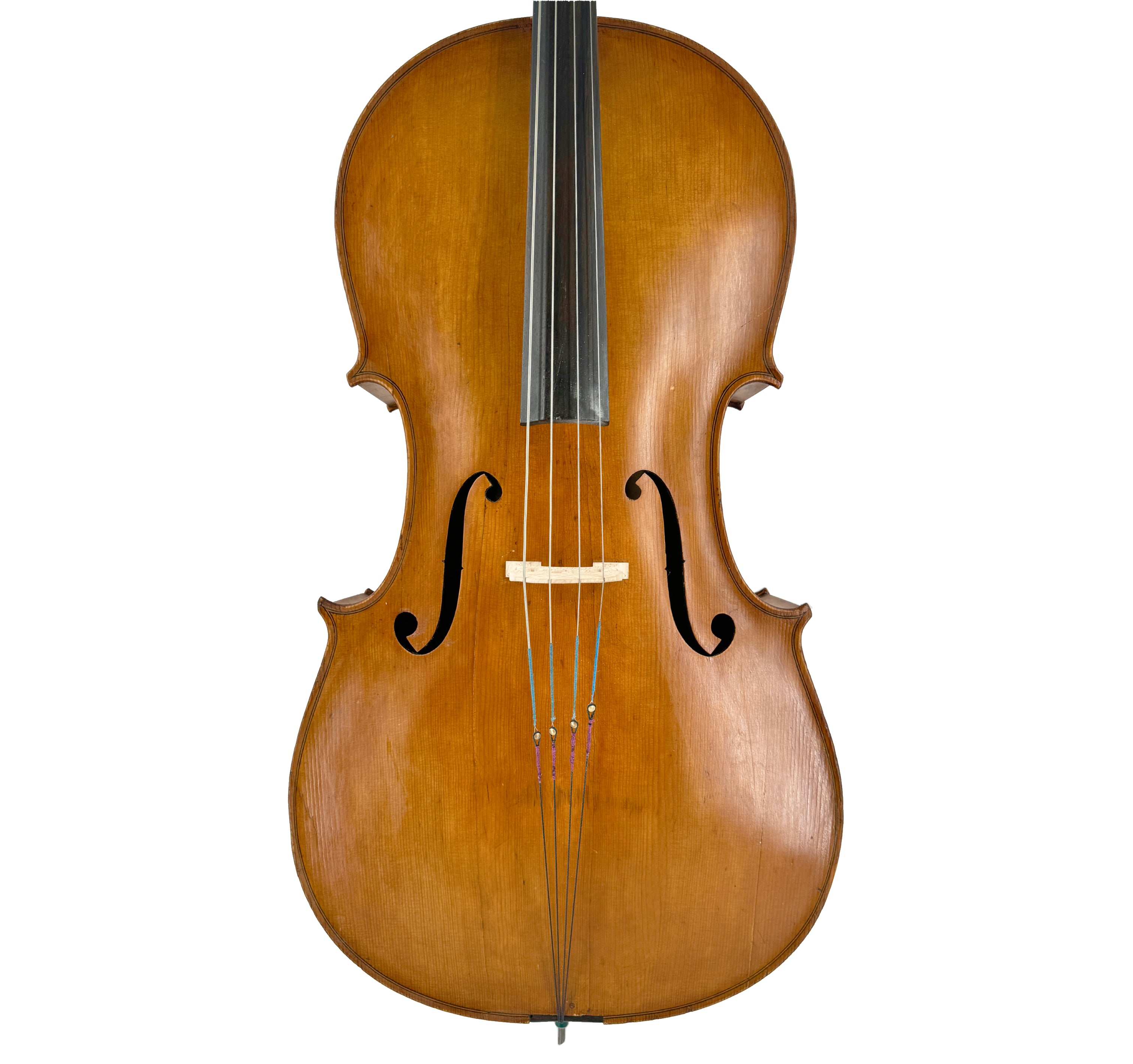
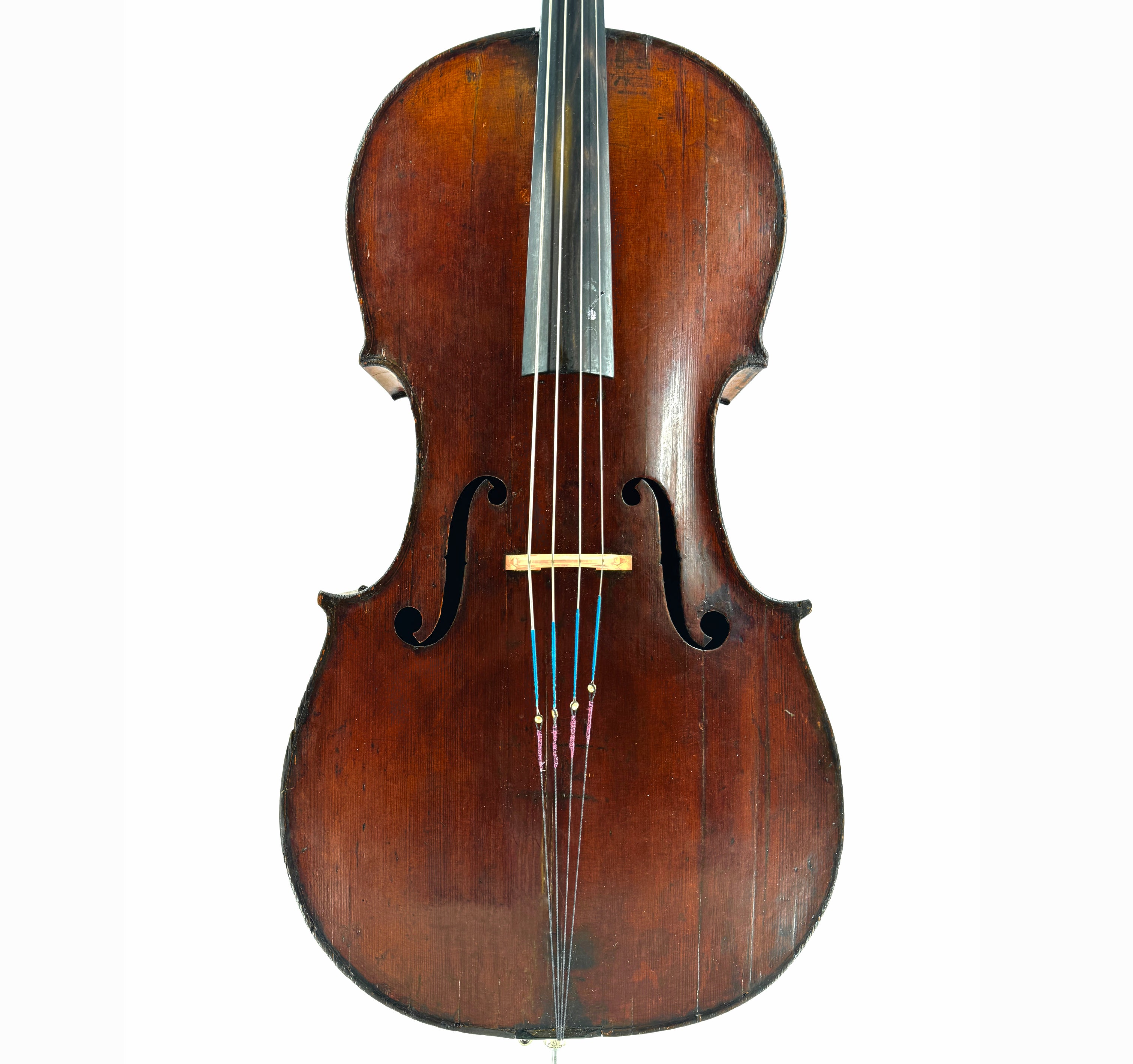
A liberated design utilizing woven Kevlar fiber. A component that expands overtones, resonance, sustain, vitality, responsiveness, and string independence - the Natural Tailpiece appeals primarily to common sense.
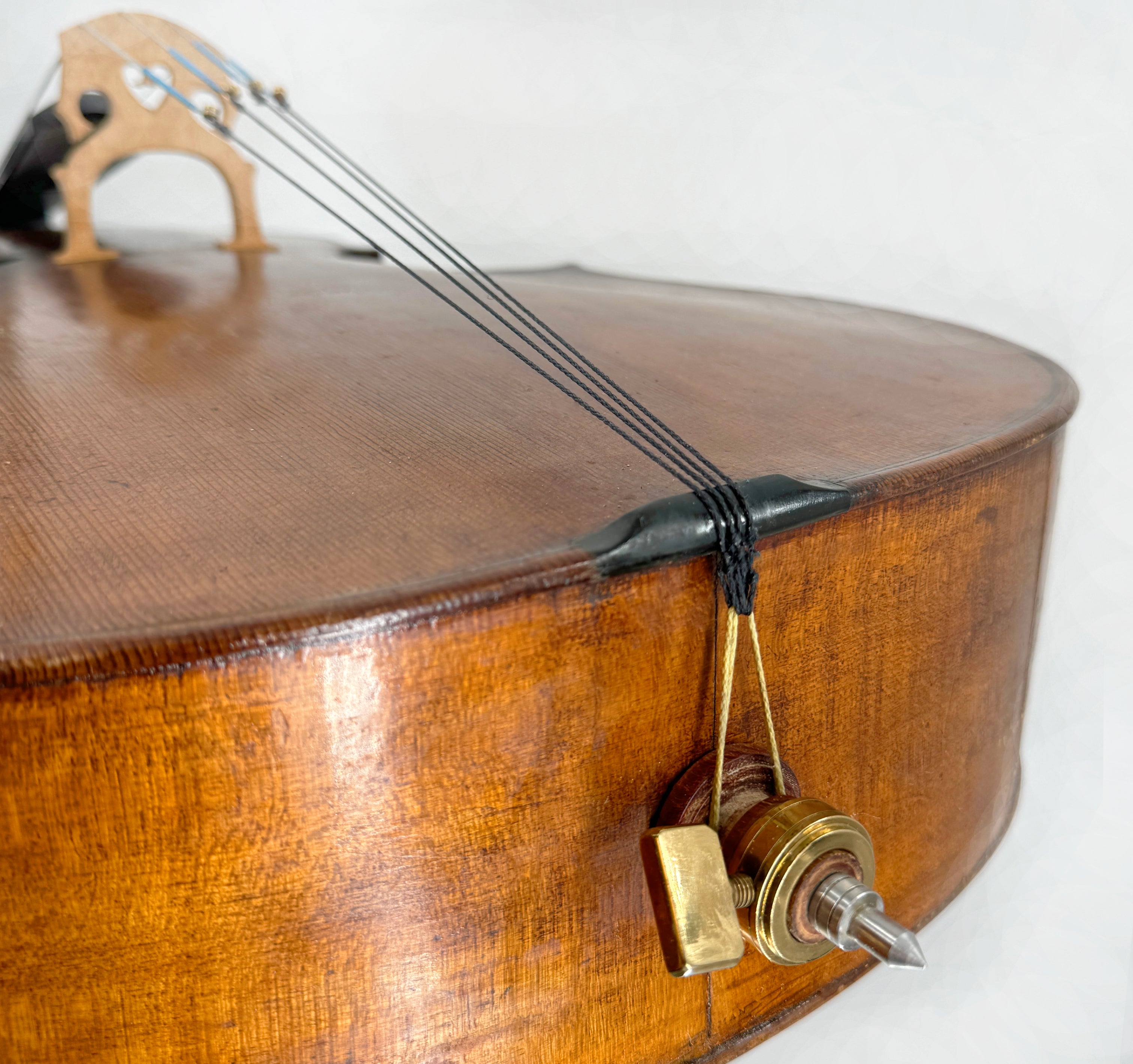
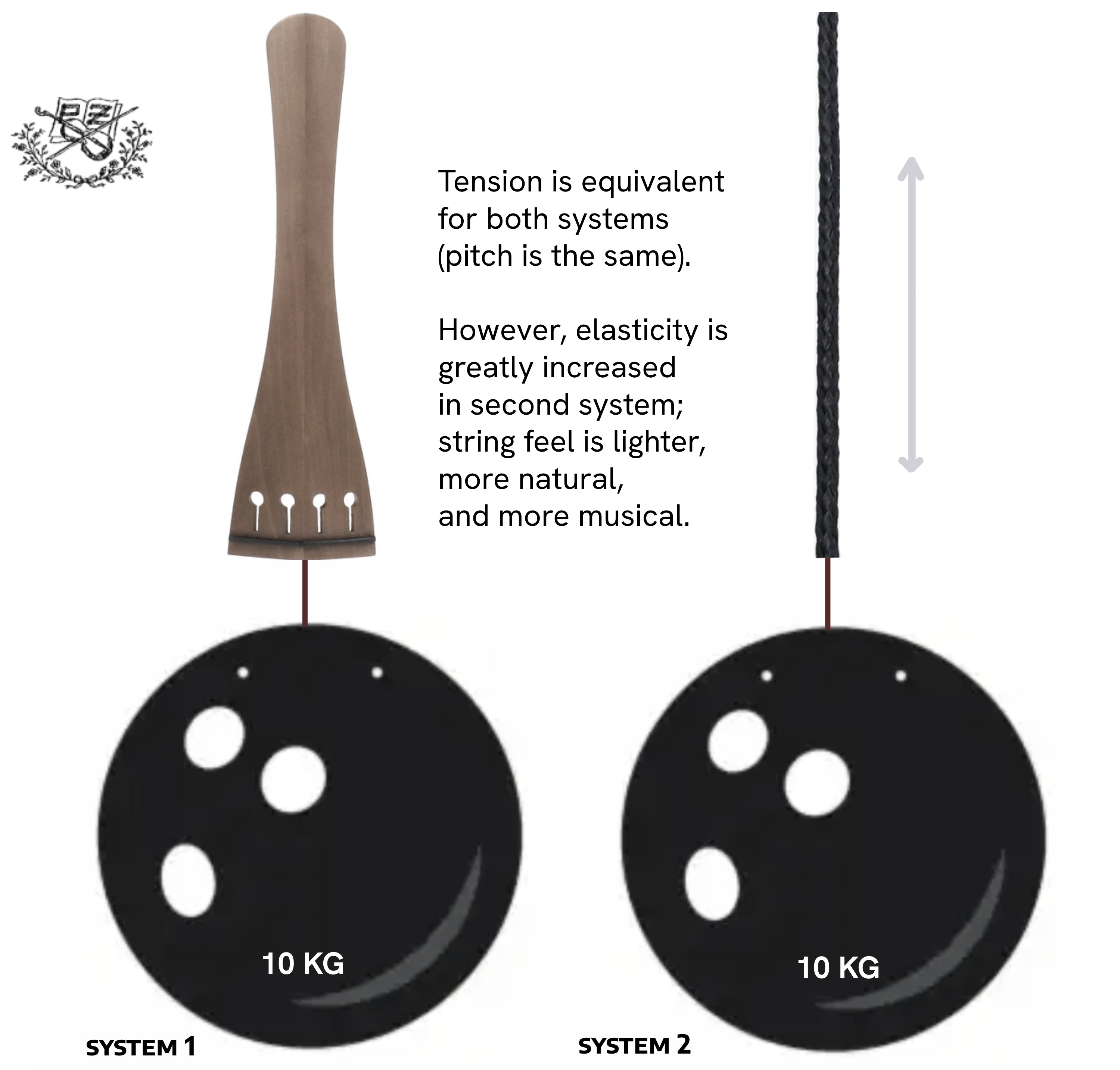
Softer string feel and a more natural playing action accelerates learning and technical mastery. The Natural Tailpiece essentializes the string suspension and tension mechanism, paring away the muting mass of plastic and metal that chokes and stifles your cello's innate vitality.
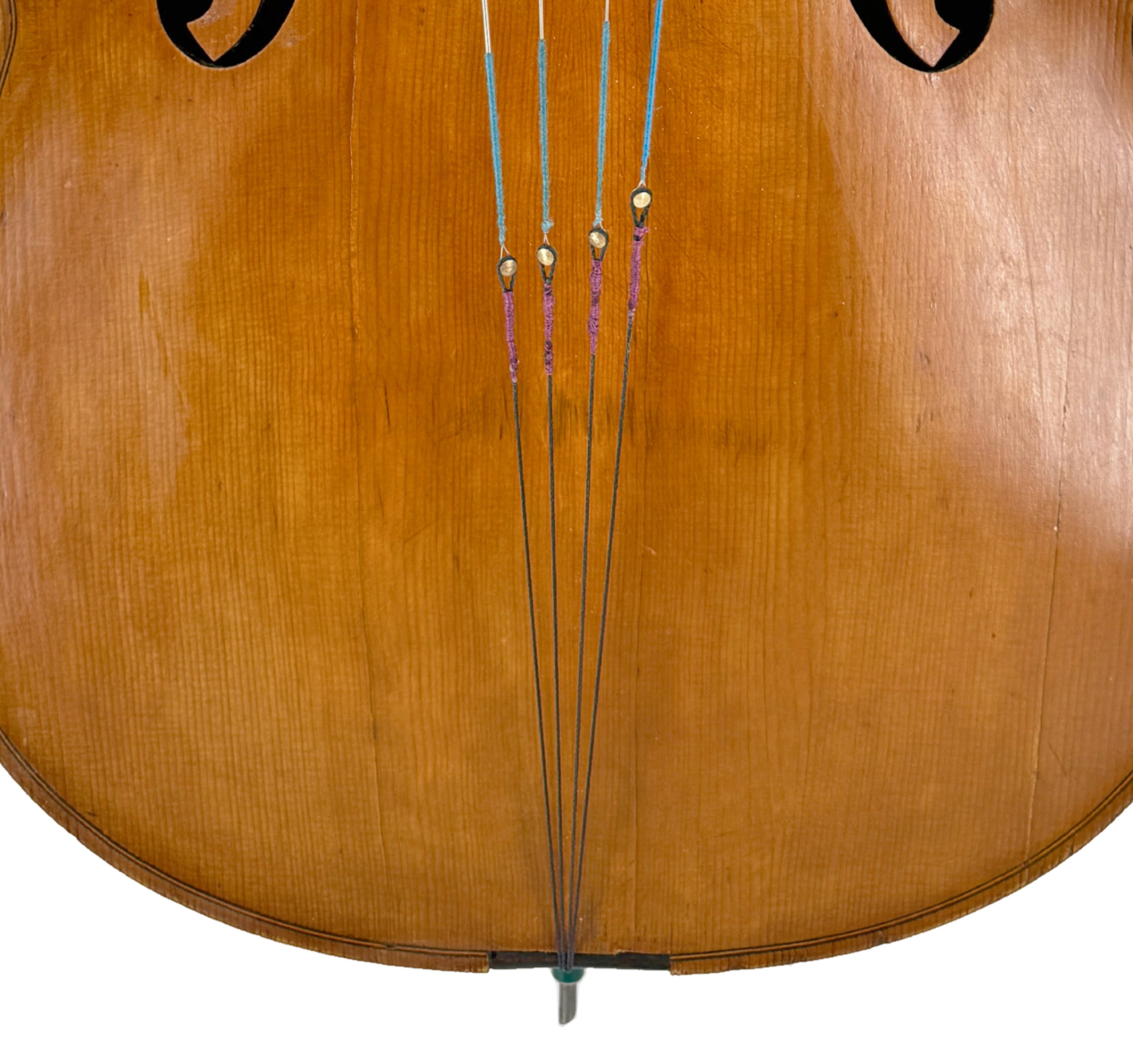
Tuning stability is also vastly improved - the tension of a single string does not influence any other string as it does when attached to a common floating plastic or wooden tailpiece. Each string terminates at a solid fixed point - the saddle - isolating the string's tension and unique harmonic and overtone profile.
Traditional silk wrap tidies up the appearance and adds an aristocratic feel; silk available in PZ Purple or Black.
Some considerations for your new tailpiece:
- Kevlar string exhibits a break-in period much like a steel string; a few hours of playing and tuning is a typical break-in period. However, once broken in, the Kevlar tailpiece will not respond to changes in humidity and temperature as does wood and steel, resulting in greater overall tuning stability.
- Geared tuning pegs are highly recommended with this tailpiece. Some cellists are adept at traditional peg tuning without fine tuners; most however will find geared tuning pegs necessary and ultimately a much more sensible and efficient peg arrangement. We are happy to install geared pegs for you at Peter Zaret and Sons Violin Shop in Cleveland, Ohio - a simple outpatient procedure we can do while you wait.
- Several equally effective methods for inserting the string ball end into the tailpiece loop are possible. You may wish for the Kevlar loop to capture the full ball end of the string, or wrap around the outer groove of the ball end (as shown in product photography). If you use strings with a loop end (gut strings etc.), please request a ball end to be shipped with your tailpiece free of charge. Ultimately, you will likely find that strings sit under tension more simply and elegantly and therefore last longer with the Natural Tailpiece.
Pickup available at 5767 Mayfield Road
Usually ready in 24 hours
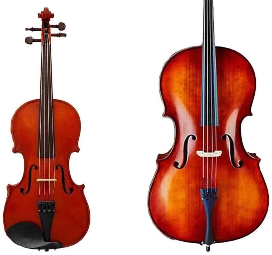
Natural Tailpiece for Cello
Black / 4/4
5767 Mayfield Road
5767 Mayfield Road
Mayfield Heights OH 44124
United States